
vSphere Networking Basics
In this article, I discuss some of vSphere’s networking aspects, something you probably have come across when using VMware software. In the first half of this article, I’ll talk mainly about the vSphere Standard Switch (vSS) in context of setting one up and configuring it on a standalone ESXi host (not managed by vCenter Server). I’ll also go over VMkernel adapters, port groups and some of the standard switch settings.
In the second half, I’ll also introduce another type of virtual switch called the vSphere Distributed Switch which is only available one vCenter Server has been installed.
Table of Contents
The vSphere Standard Switch
A vSphere Virtual Switch, allows a number of virtual machines connected to it to communicate with one another, pretty much like their physical counterparts would when connected to a physical switch. In addition, the vSS bridges virtual networks to physical ones using the ESXi host’s network cards, on which the vSS has been created, as uplink ports to a physical switch.
By default, a standard switch is automatically created when you install ESXi. This is labelled vSwitch0 as per Figure 1.
Note: An uplink port is simply a designated port on a networking device such a switch or a router that connects or cascades one piece of networking equipment to another. Figure 1 shows how the two physical adapters – labelled 3 – on the ESXi host set up for this post have been designated as uplink ports.
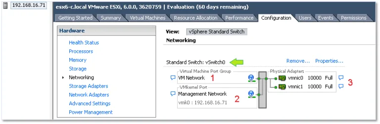
Looking closely at Figure 1, you should also notice the headings Virtual Machine Port Group and VMkernel Port denoted by 1 and 2 respectively. I’ll explain what these mean in the upcoming sections.
Port Groups
A port group, as the name implies, is a grouping of switch ports. By applying a network policy to a port group, one can enforce security and traffic shaping rules. Additionally, if you have VLANs set up on your physical switches, you can assign a VLAN ID to a port group such that any VM on it will, for all intents and purposes, reside on that specific VLAN.
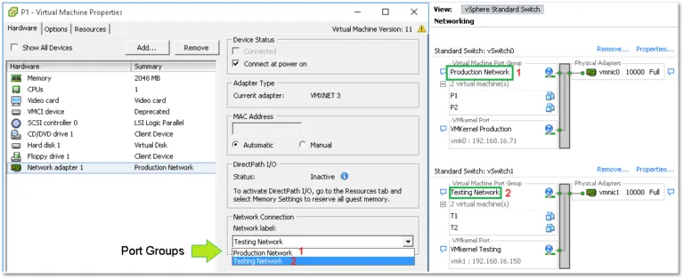
When you create a network-enabled virtual machine, you are in fact connecting its virtual adapters to one or more port groups. Figure 2 illustrates this aspect. The VM properties, including the selected port group, are shown on the left side of Figure 2 while the switch settings – where port groups are defined – are shown on the right. In this instance, I created two vSphere standard switches each having a distinct port group. Notice how each switch has its own dedicated uplink (vmnic0 and vmnic1).
TIP: If there’s a need to isolate one or more virtual machines from the rest of the network, whether physical or virtual, you can simply create a standard switch with no specified physical adapters (uplinks). Any virtual machine placed on the switch’s associated port group will still be able to talk to any other VM on the same port group but will be completely cut off from other networks. Such a setup comes in handy whenever you need to replicate, say, a live environment in keeping with the same layer 3 addressing (IPv4/6) but without impacting any of the production systems.
The VMkernel
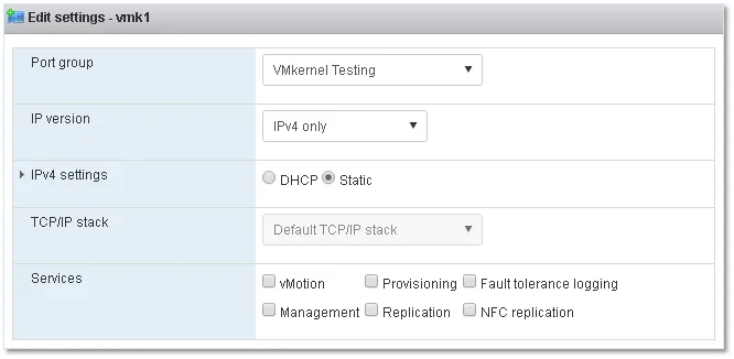
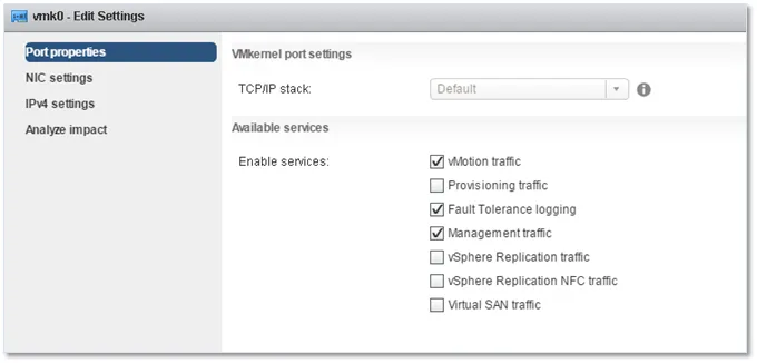
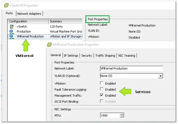
The VMkernel network interface, adapter or port is basically a service provider used by the ESXi host to communicate with the outside world and the rest of the VMware based infrastructure. VMkernel adapters are created according to the type of services required by vMotion, Fault Tolerance, Management or perhaps vSAN. A list of services necessitating of a VMkernel are depicted under Services in Figures 3 and 4. A VMkernel is assigned an IP address using either DHCP or one which is assigned manually, the latter option being, in my opinion, the most sensible one.
By default, vmk0 is the first VMkernel adapter created which is enabled for management traffic. Interestingly enough, you’ll still be able to connect to ESXi if Management is ticked off.
After creating a VMkernel you’ll come across something that looks like a port group but not quite. This is, in fact, a port. Depending on the tool used to create it, things can get somewhat confusing. For instance, when using the C# vSphere client, you’d be forgiven for thinking that the VMkernel is, in fact, a port group since the same icon is used for both:
vSphere Networking Maximums
Before I move on, I’m going to list a few vSphere 6.0 maximums related to standard switches:
- 512- Port groups per standard switch.
- 1016 – Maximum active ports per host.
- 4096 – Total virtual network switch ports per host.
- 4088 – Virtual network switch creation ports per standard switch.
Creating a virtual standard switch
There are a number of ways to create a standard switch. These include PowerCLI, ESXCLI, the standard and Web vSphere clients and the recently introduced VMware Host Client assuming you’ve made the transition to ESXi 6.0 update 2. Here’s a quick rundown.
ESXCLI
Use something like putty to SSH to the ESXi host and run the following command to create a 24 port switch called myVSS.
esxcli network vswitch standard add -P=24 -v=myVSS
PowerCLI
Connect to the ESXi host using the Connect-VIServer cmdlet and then issue the following to create the same switch as per the ESXCLI command.
New-VirtualSwitch -name myVSS3 -NumPorts 24
Note: Starting with ESX 5.5, switches are created elastic meaning there is no need to specify the number of ports since these are added dynamically as required. I’ve included the parameter just for completeness sake. In fact, in the case of PowerCLI, the ports parameter is completely ignored.
Thick vSphere Client
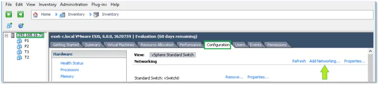
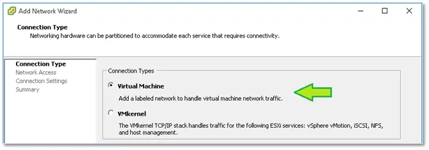
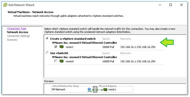
When using the vSphere clients, simply highlight the ESXi host on which you want to create the switch, change over to the Configuration tab and click on Add Networking as shown in Figure 6-9. Next, choose Virtual Machine (if this is not misleading, I don’t know what is) binding it to a physical nic as well as creating a new port group for it.
VMware Host Client
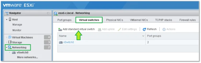
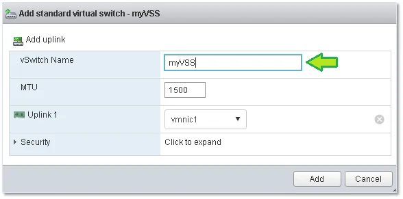
If you have ESX 6.0 U2 (or have installed the fling) you can also use the VMware host Client to create a standard switch. Once you log in, select Networking from Navigator and switch to the Virtual Switches tab. Click on Add standard virtual switch and fill in the details. It’s as simple as that.
Configuring a standard switch
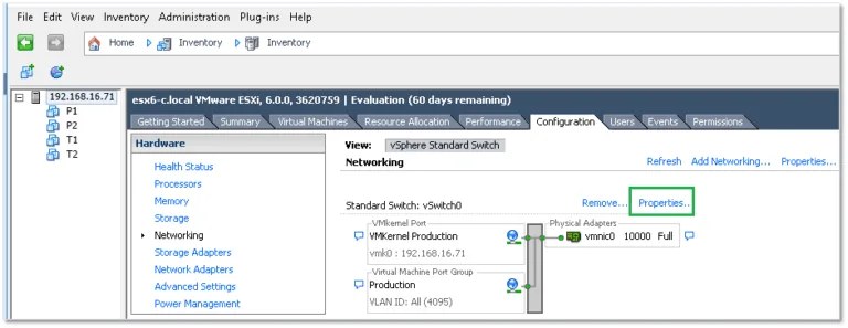
For this section, I’ll be using the C# vSphere client and an ESXi 6.0 U2 setup. Just as a reminder, vSwitch0 is created automatically as part of the ESXi installation process.
To view the switch’s configuration, highlight the host’s IP address or hostname, select the Configuration tab and select Networking under Hardware. Click on Properties as shown in Figure 6.
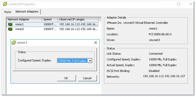
On the next screen, you’ll find 2 tabs, one called Ports (probably for lack of a better name) and another called Network Adapters. I’ll start with the latter since I’ll refer to it later on. This is basically where you will bind the physical ESXi host’s network cards to the virtual switch. Binding two or more NICs will provide for link aggregation and failover options.
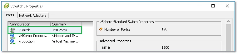
Under the Ports tab – as far as vSwitch0 is concerned – you’ll find three items created automatically when ESXi was first installed. These are the vSwitch configuration, a default port group and a VMkernel. You’ll be able to add other port groups and VMkernels using the Add button at the bottom of the vSwitch properties window.
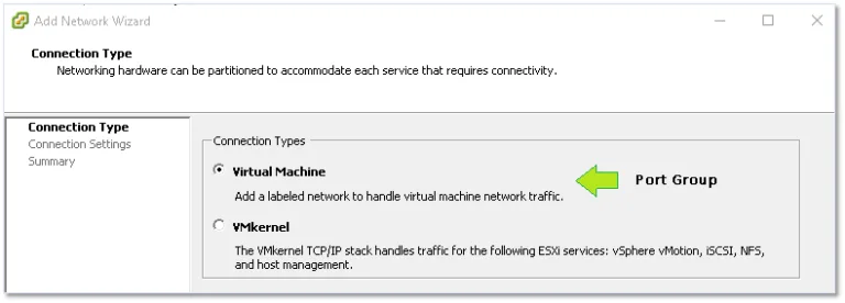
Once again, things can get a little bit confusing depending on the client or method used to create and manage networking. As shown in Figure 15, you’ll need to select Virtual Machine as the connection type if you want to create a new port group.
To view the virtual switch settings, just click on the Edit button. Here you’ll find 4 tabs related to the switch’s network policy comprising various options and settings that govern both the switch and how it handles traffic. Again, depending on the tool used, some options may or may not be available. For instance, NIC Teaming is unavailable when using the VMware Host Client (at least, I wasn’t able to find it listed anywhere).
Standard Switch Settings and Policies
The switch’s configuration is accessed by clicking on the Edit button while the vSwitch configuration item is highlighted. This brings up a window with the previously mentioned tabs. Keep in mind that the settings and options set at the vSwitch level will percolate down to every other item in the configuration list. That said, an override option is available for each and every item.
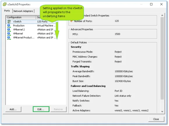
Let’s go over the settings / option found under each tab.
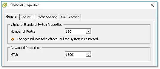
General
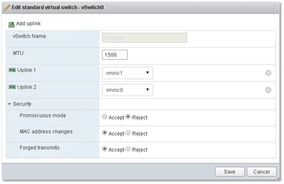
Here you’ll set the number of switch ports required (max. 4088) and the MTU (Maximum Transmission Unit) size. The latter is generally changed if jumbo frames are enabled on your networks.
Security
Under the Security tab, you’ll find 3 settings defining the security policy for the switch.
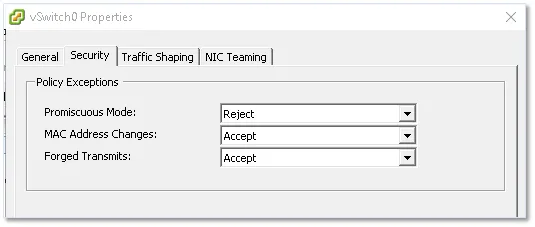
The settings available are as follows;
- Promiscuous Mode – If set to accept, any VM on the switch having a virtual adapter in promiscuous mode will be able to eavesdrop on all the traffic passing through the switch.
- MAC Address Changes – Determines what happens when the MAC address of a network adapter on a VM is changed. If set to Reject, all traffic emanating from the VM is dropped when the MAC address supplied does not match that found in the VM’s vmx configuration file.
- Forged Transmits – If set to reject, frames with spoofed source MAC addresses will be dropped.
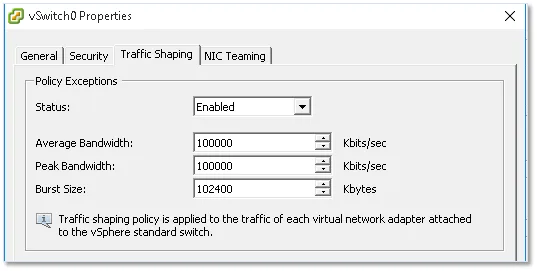
Traffic Shaping
The traffic shaping policy, if enabled, regulates bandwidth and burst size on the switch. This may come in handy when a number of port groups are created on the switch and you wish to apply a traffic utilization baseline across all port groups. Yet again, such a policy can be overridden if required for each and every port group.
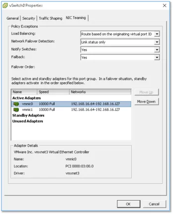
NIC Teaming, Failover and Load Balancing
If you have 2 or more physical ESXi NICs bound to a virtual switch, you will be able to increase bandwidth availability using either Ether Channel or Link Aggregation Control Protocol (LACP). This may require familiarity with some advanced networking concepts (depending on your background) which I’m not going to discuss here.
Under the NIC Teaming tab you’ll find a number of failover options. In the example below, I have two physical NICs set up as Active Adapters. This ensures that the uplink is maintained if any one adapter goes offline. I could also move one adapter to the Standby Adapters group. When you do this, the standby adapter will only become active when all the NICs within the Active Adapters group fail.
Configuring a port group
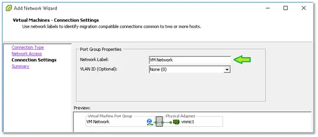
Most of the settings just covered equally apply when configuring a port group, the main difference being those found under the General tab.
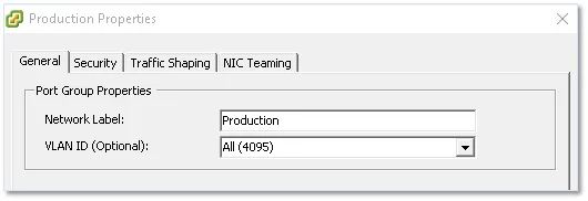
The Network Label setting is self-explanatory. This is the name you assign to the port group and is what you see listed when you connect a VM’s virtual adapter to a network. The VLAN ID setting is on the other hand slightly more interesting albeit optional. If you have VLANs set up on your physical switches, ESXi operates in 3 different ways to take VLANs into account, these being;
- External Switch Tagging (EST) – This is required when VLAN tagging of packets is performed on the physical switch. The ESXi host’s network adapters are in this case connected to access ports on the physical switch. The VLAN ID must be set to 0.
- Virtual Switch Tagging (VST) – Contrary to EST, all VLAN tagging is carried out by the virtual switch before leaving the host. Host network adapters must be connected to trunk ports on the physical switch. Port groups connected to the virtual switch are assigned a VLAN ID between 1 and 4094.
- Virtual Guest Tagging (VGT) – With VGT, all VLAN tagging is done by the virtual machine. VLAN tags are preserved between the virtual machine networking stack and external switch when frames pass to and from virtual switches. Host network adapters must be connected to trunk ports on the physical switch. For a standard switch, the VLAN ID of port groups with VGT must be set to 4095.
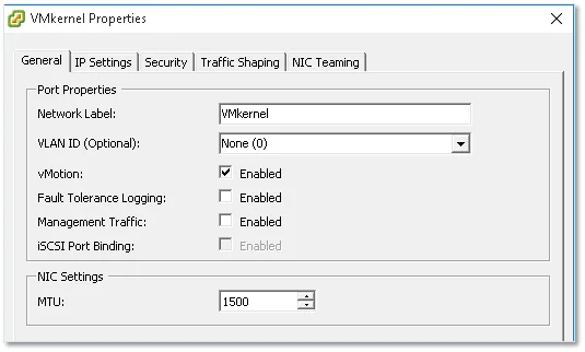
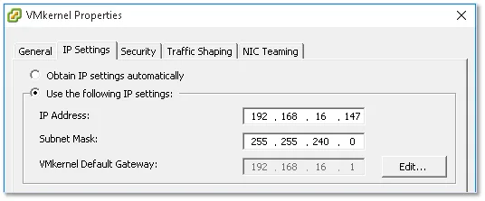
Configuring a VMkernel
There are 2 main aspects to configuring a VMkernel, its IP address and the services it provides. Under the General tab, you can specify a name for the VMkernel, the services provided as well as an MTU value if you’re using anything other than the default value of 1500. Under the IP Settings tab, you’ll find settings for the IP address and network mask. The remaining tabs are again identical to the ones previously covered with all the settings being inherited but which can nevertheless be overridden.
Interim conclusion
I think I covered the salient aspects of vSphere standard switches and even though there’s probably more than can be said, I need to draw a line somewhere lest this ends up being one ginormous post. Next, I’ll cover distributed switches, a useful feature when managing multiple hosts via vCenter Server, and anything else that might have fallen between the cracks. I will also tackle the vSphere Distributed Switch (vDS), a vCenter Server component or object that is used to centralize the network configuration of managed ESXi hosts. Unless standard switches are required for a specific reason, a vDS voids the need to create a standard switch on every ESXi host. This boils down to the fact that a vDS’ configuration is pushed to any ESXi host that is hooked up to it. Let’s have a quick look at the architecture first.
The architecture of a vDS
The next diagram, kindly reproduced from the VMware site, shows the vDS’ architecture and how the management plane is kept separate from the data plane as opposed to what happens on a standard switch. This partitioning scheme makes it possible to roll out one distributed switch across a number of hosts as opposed to creating a standard switch on every host. The management plane, in case of vDS, resides on the vCenter Server while the data plane, also referred to as a host proxy switch, is local to the ESXi host. This is the primary reason why vCenter Server needs to be installed if distributed switching is in your bucket list.
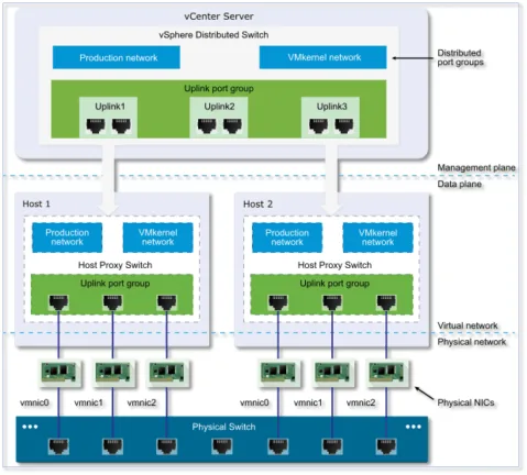
The vDS also introduces a couple of new abstractions namely the Uplink Port Group and the Distributed Port Group. Below is an explanation for each:
Uplink port group: An uplink port group or dvuplink port group is defined during the creation of the distributed switch and can have one or more uplinks. An uplink is a template that you use to configure physical connections of hosts as well as failover and load balancing policies. You map physical NICs of hosts to uplinks on the distributed switch. At the host level, each physical NIC is connected to an uplink port with a particular ID. You set failover and load balancing policies over uplinks and the policies are automatically propagated to the host proxy switches, or the data plane. In this way you can apply consistent failover and load balancing configuration for the physical NICs of all hosts that are associated with the distributed switch.
Distributed port group: Distributed port groups provide network connectivity to virtual machines and accommodate VMkernel traffic. You identify each distributed port group by using a network label, which must be unique to the current data center. You configure NIC teaming, failover, load balancing, VLAN, security, traffic shaping, and other policies on distributed port groups. The virtual ports that are connected to a distributed port group share the same properties that are configured to the distributed port group. As with uplink port groups, the configuration that you set on distributed port groups on vCenter Server (the management plane) is automatically propagated to all hosts on the distributed switch through their host proxy switches (the data plane). In this way you can configure a group of virtual machines to share the same networking configuration by associating the virtual machines to the same distributed port group.
Creating a vDS
For the remaining how-tos in this post, I’ll be using the vSphere Web Client. The vSphere setup I am using here consists of a virtualized vCenter Server 6.0 U1 managing two nested (virtualized) ESXi 6.0U1a hosts.
To create a new distributed switch, follow these steps;
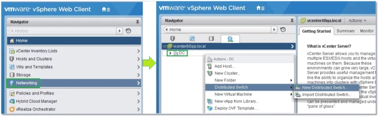
Once you’ve logged in vCenter Server using the vSphere Web client, select Networking from Navigator. With the Datacenter name highlighted, in this case DC, right-click on it selecting New Distributed Switch from the Distributed Switch sub-menu (Figure 2).
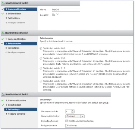
Proceed by completing the information asked for by the wizard, in this order;
1) Specify a name for the switch
2) Select the switch version. Distributed switches created in earlier versions can be upgraded to the latest to leverage new features.
3) Edit the settings of the vDS:
- Specify the number of uplink ports (see Part 1)
- Enable Network I/O control, if supported, to monitor I/O load and assign free resources accordingly
- Optionally, create a corresponding distributed port group and set a name for it
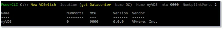
Similar to what I covered in the first article of this series, you can use PowerCLI to create a distributed switch on vCenter using the following example. Note that the location parameter is mandatory. I’m already connected to the vCenter Server on which I want the switch created via the Connect-VIServer cmdlet.
New-VDSwitch -location (get-Datacenter -Name DC) -Name myVDS –
mtu 9000
-NumUplinkPorts 2
So far we have simply created an empty switch. The next step is to add hosts to it.
Adding hosts to a vDS
Having created the distributed switch, we can now add the ESXi hosts we’d like connected to it. Before proceeding, however, make sure that;
- There are enough uplinks available on the distributed switch to assign to the physical NICs you want to be connected to the switch.
- There is at least one distributed port group on the distributed switch.
- The distributed port group has active uplinks configured in its teaming and failover policy.
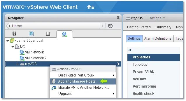
To add hosts to the vDS, simply right-click on the name of the vDS just created and select Add and Manage Hosts.
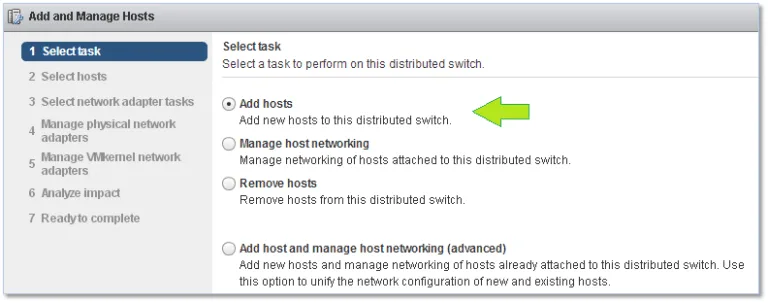
The first screen of the wizard presents a number of options but this being the first time we’re adding hosts to the vDS, the only options that really interest us are Add hosts and Add host and Manage host networking. I’m going by the first.
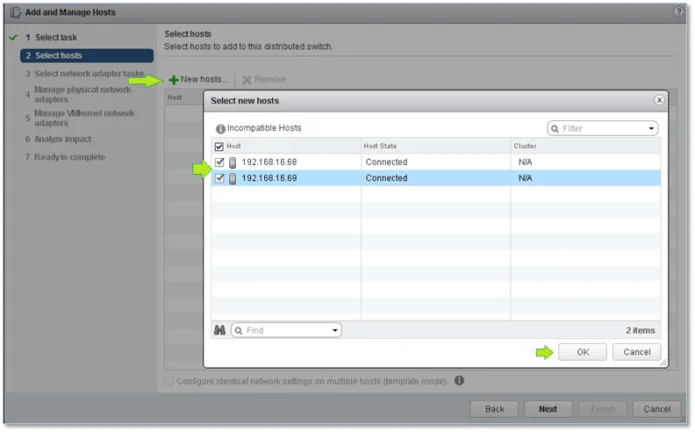
Click on New hosts and, on the secondary window, tick the check-box next to whichever host you want to be connected to the vDS. Click Next when done.#
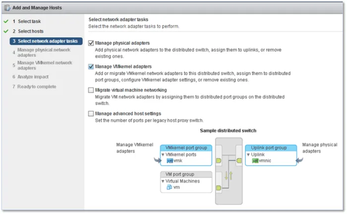
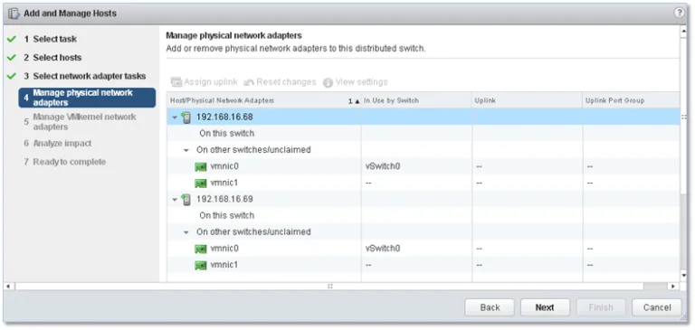
Yet again, you are presented with a number of options. In the figure below, I’ve chosen to add uplinks to the switch as well as migrate any VMkernels, set up on the hosts (set up on standard switches), to the vDS by selecting the first two options.
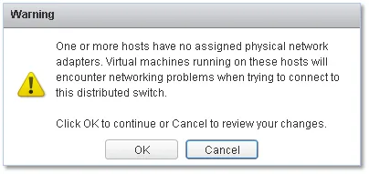
The next screen gives you a summary of what’s available on the host in terms of physical NICs. A warning pops up if any of the NICs are found to be already bound.
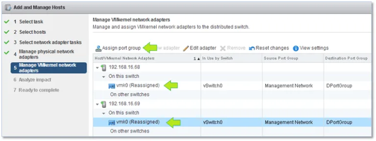
The next step helps you to migrate any existing VMkernels to the vDS’ port group. To do so, highlight the VMkernel you wish to migrate and click on Assign port group. Select the required port group from the secondary window.
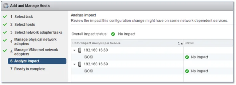
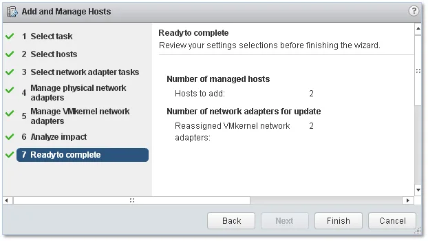
Next, an impact analysis is carried out where checks are made to ensure that running services are not impacted by the network changes being done.
Click Finish to finalize the Add and Manage Hosts process.
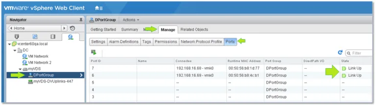
In order to verify that all the VMkernels marked for migration have been correctly moved, select the vDS’ port group from Navigator and switch to the Manage tab. On the Ports screen, you should be able to see the migrated VMkernels each assigned to a respective port on the vDS. The link-state for each should also be up.
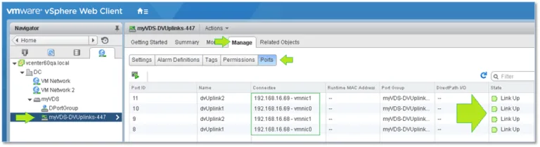
Likewise, you should make sure that all hosts report as active on the vDS. To do so, select the distributed port group object from Navigator and verify that the uplinks are up.
Migrating virtual machines to the vDS
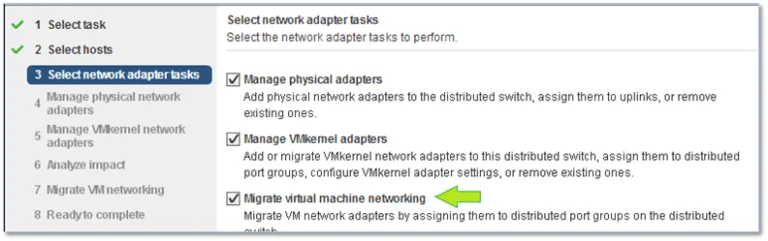
Once you’ve switched over – excuse the pun – to using distributed switches instead of standard ones, you’ll find that any virtual machines set to use port groups created on a standard switch will be left in a networking limbo unless you happened to select Migrate virtual machine networking during the vDS’ host assignment process as shown in this image:
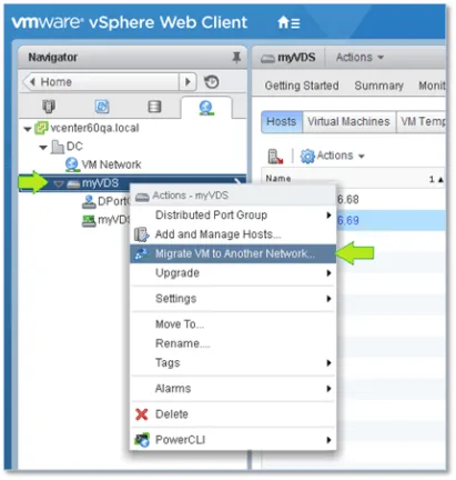
Alternatively, this can easily be rectified by changing the port group assignment from the VM’s properties. However, if there are a significant number of VMs to migrate, the migration wizard is definitely the way forward. To initiate the migration process, right-click on the vDS’ name under Navigator and select Migrate VM to Another Network.
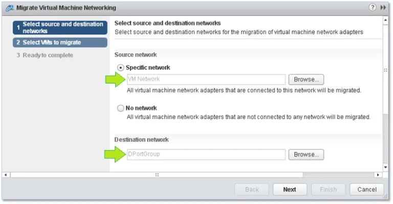
At the first screen, select the source and destination port group. As the Source network, I’ve chosen a port group called VM Network previously set up on every standard switch created. DPortGroup is the destination network on the vDS to which the VM will be migrated.
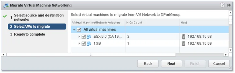
On the next screen, select the VMs you want to be migrated to the new port group. Tick the box next to whichever VM’s networking you want to be migrated or simply tick the box next to All virtual machines to move the whole lot. Click Next and Finish (the last screen not shown) to finalize the migration process.
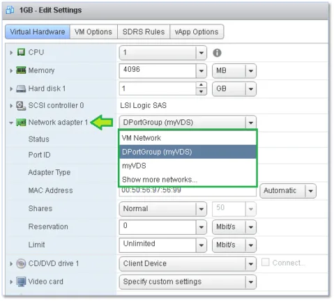
Alternatively, and as mentioned, any VM can be reassigned to any port group by changing the same from the network settings.
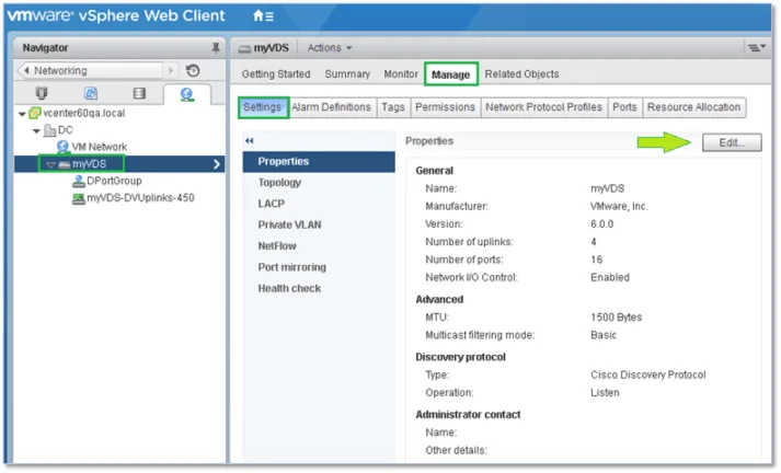
vDS Settings
There are a number of settings extra to those found on standard switches. Similarly, you’ll find a bunch of configuration settings applicable to the switch itself as well as the distributed port and uplink groups created.
The switch settings are accessible by clicking on the Edit button shown in Figure 21. In addition, you can configure advanced features such as port mirroring, allowing you to mirror traffic from one port to another for analytical and diagnostic purposes and private VLANs which are used to overcome the limitations of VLAN IDs by further segmenting broadcast domains into smaller sub-domains. You can also enable and configure Cisco’s NetFlow protocol to monitor IP traffic and aggregate links for greater bandwidth using LACP.
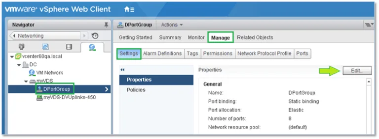
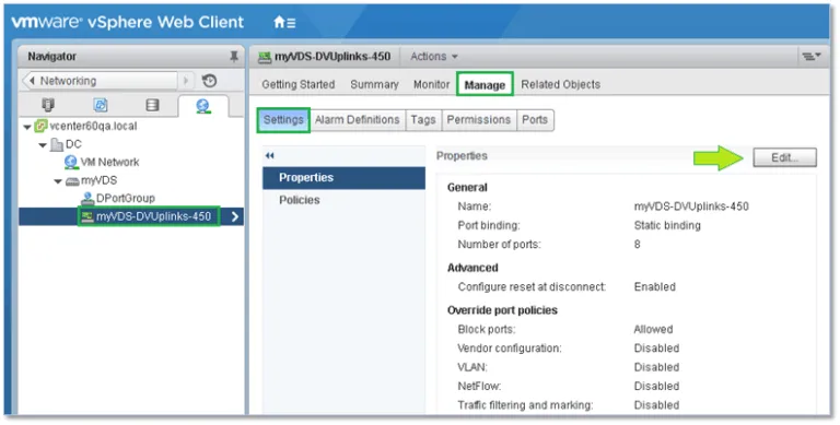
Similarly, the distributed port and uplink group settings are accessible by clicking on the Edit button shown in these two images:
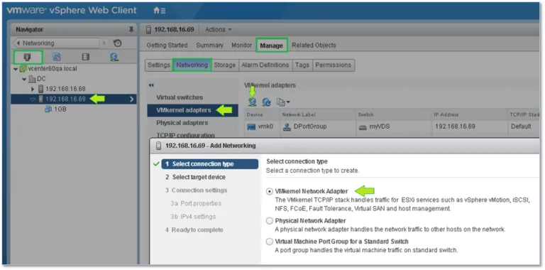
Something important you should keep in mind is that you still have to set up and configure VMkernel adapters on a per-host basis similar to what you have been doing with standard switches.
There are more options you will need to explore many of which are documented in great detail on the VMware documentation site. I cannot possibly go into each and every option as I would end up replicating what’s already available out there making this post a never-ending one.
TCP/IP Stacks
One last feature I’d like to talk about is TCP/IP stacks, in particular how they can be used to segregate the network traffic associated with a particular service ultimately improving performance and security.
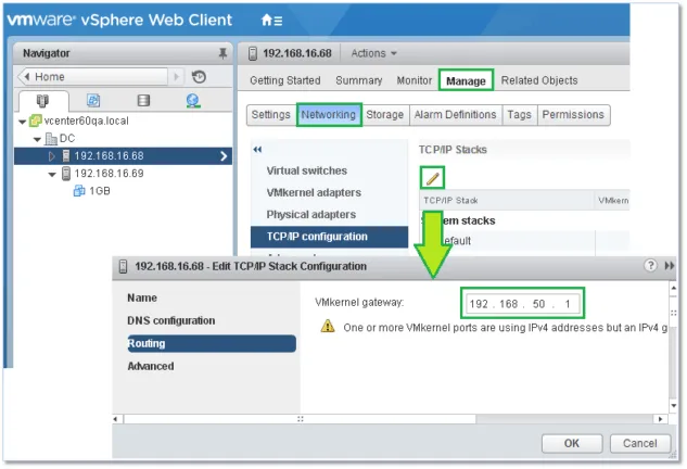
By default, vSphere provides three TCP/IP stacks with these being the default, vMotion and provisioning stacks which can all be configured from the TCP/IP configuration screen of an ESXi host as shown below.
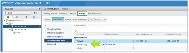
Each stack can have its own default gateway and DNS configuration meaning any service bound to a particular stack will effectively be running on its own network if configured as such. In addition, you can also choose the type of congestion control algorithm and the maximum number of allowed connections.
Stack Types
Default – This stack is generally used for management traffic, vMotion, storage protocols such as iSCSI and NFS, vSAN, HA, etc.
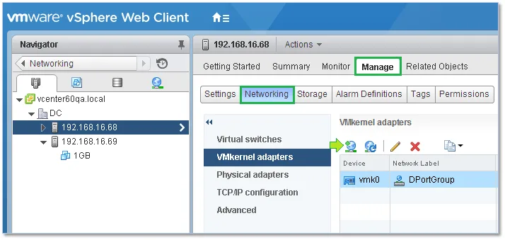
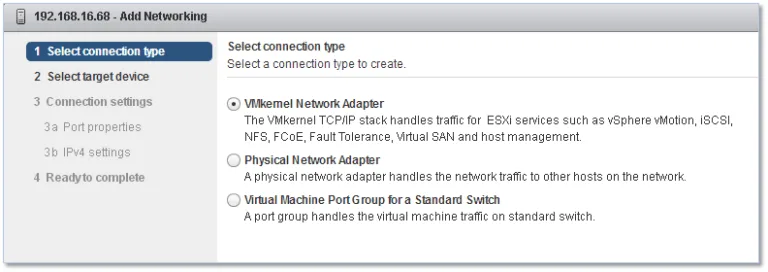
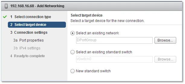
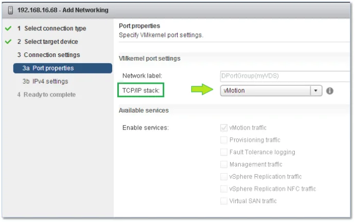
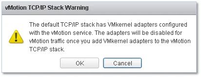
vMotion – This stack is used when wanting to isolate vMotion traffic. To achieve this, create a VMkernel on every host configured for vMotion and set the kernel to use the configured vMotion stack. The steps are as follows;
Provisioning – This stack is generally used to isolate traffic related to cold migrations, cloning and snapshots.
If required, you can use ESXCLI to create custom stacks. The command is as follows;
esxcli network ip netstack add -N=”stack_name”
Conclusion
In this series, we learned the differences between standard and distributed switching together with a brief explanation on port groups, VMkernels, VLANs and a few other topics. The information presented is by no means exhaustive but it should suffice to get you started with the networking side of vSphere. As always, the best way to learn is to experiment and try things out for yourself.